With the sunset of Morehouse Cowles, DisperseTech now offers compatible impeller blades for legacy mixers. Customers...

Search in blog
Blog categories
Latest posts
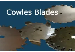
Morehouse Cowles Sunset – DisperseTech Offers Compatible Impeller Blades
Read more
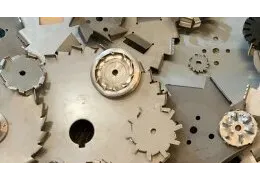
Unleashing the Power of Dispersion Blades: A Comprehensive Guide to Enhanced Mixing Efficiency
Read more
In the dynamic world of mixing processes, the efficiency of your equipment can make or break your operations. Enter...
Popular posts

Properties of Common Solvents
Density, boiling point, evaporation rate, and flash point of common solvents
Read more

Tip Speed Definition and Formula
Blade Speed (tip speed), measures how far a point on the outer most edge of the disperser blade travels in a given...
Read more
CLEARANCE HOLE CHART
Clearance hole chart for inch bolts and screws according to ASME B18.2.8
Read more

Paint Formulation
Paint consists of four basic components:
Resin
Pigment
Solvent
Additives
The performance of a coating is influenced...
Read more
Viscosity Conversion
Viscosity Conversion table comparing some of the typical viscosity scales used in Paint and Coatings including:...
Read more
Latest comments
-
 MalcomizingWe have a customer that needs parts Malcomized, could you...
 -
electricianGreat technical overview! This blog clearly explains...
-
electricianClear overview of different electrical service types and...
-
Blade to mix sand into paintUsed to have a Teflon on plastic blade need one for my...
-
cpvc & paint mix formulavery good excellent OK
Featured posts
Morehouse Cowles Sunset – DisperseTech Offers Compatible Impeller Blades
With the sunset of Morehouse Cowles, DisperseTech now offers compatible impeller blades for legacy mixers. Customers...
Read more
Unleashing the Power of Dispersion Blades: A Comprehensive Guide to Enhanced Mixing Efficiency
In the dynamic world of mixing processes, the efficiency of your equipment can make or break your operations. Enter...
Read more
CLEARANCE HOLE CHART
Clearance hole chart for inch bolts and screws according to ASME B18.2.8
Read more
Blog tags
No featured images
Archived posts
Top authors
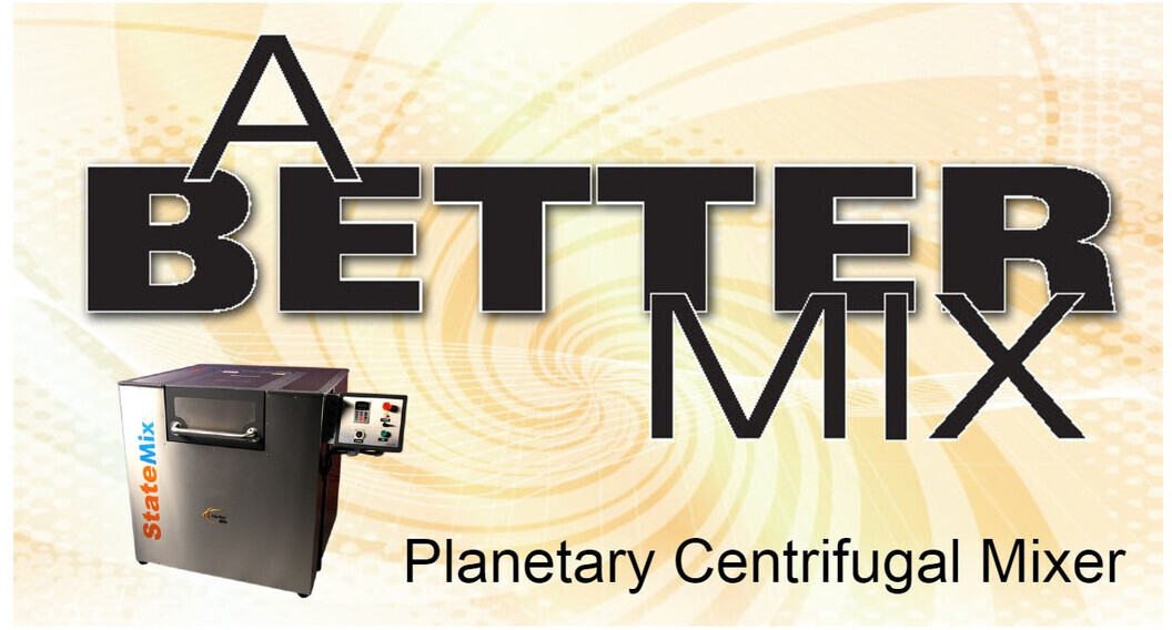
Dual-Axis Centrifugal Mixer - A Better Mix
Jacketed tanks/reactors are commonplace in the chemical industry. Many batch operations in the chemical industry require both heating and cooling at different times in the process. Rapid changes in temperature of the heat transfer media can thermally shock the equipment. Typically, thermal shock is defined as changing the cooling or heating media at the jacket inlet more than 25 F per minute. Thermal shock can be avoided by tempering the heat transfer media and providing proper venting. Tempering is easiest achieved when a common heat transfer media is used for both heating and cooling. A Temperature Control Unit (TCU) can be used to adjust the temperature of the heat transfer media at a rate that does not pose the risk of thermal shock. While TCUs are the simplest means of controlling temperature and protecting equipment many companies still insist on using different media for heating and cooling. Many times this includes steam heat and water cooling. If this MUST be done some minimum precautions should be taken.
1. HEATING to COOLING:
When changing from steam heating to cooling water one of the following procedures should be followed:
A. Forced Tempering
Vent steam out of jacket and drain condensate. Allow jacket cool down naturally or use compressed air to blow-down the jacket from top to bottom to achieve correct temperatures. Close vents and slowly introduce hot water at the correct temperature to the jacket. Increase flow rate to process conditions and decrease water temperature at a rate of less than 25 F per minute.
B. Natural Tempering
Vent steam out of jackets and completely drain all condensate. Allow the jacket to cool down naturally to the correct temperature. Close vents and introduce cooling water.
2. COOLING to HEATING:
When changing from cooling water to steam heating one of the following procedures should be followed:
A. Forced Tempering
Raise circulating water temperature in the jacket at a rate of less than 25 F per minute until desired steam temperature is reached. Vent jackets and completely drain out water. Close vents and slowly introduce steam into the jacket.
B. Natural Tempering
Vent and drain water out of jackets. Let the jacket warm up naturally to the correct temperature. Slowly introduce steam into jackets at reduced pressure and/or flow rate (temperature) until the desired steam temperature is reached. As with any manual process, there are risks associated with this.

Review of the function and operation of planetary-centrifugal mixers. Published July 2010, Adhesives and Sealants Industry Magazine
The axial flow paradigm has long been one of the most predominant mechanisms of mixing. This flow pattern is generally produced by a single-shaft mixer with axial flow impellers. It is characterized by flow down the center of the batch to the bottom of the tank, which is then deflected outward toward the wall by the container bottom. It then travels up the vessel wall and back across the surface, as shown in Figure 1.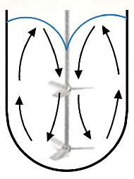
Fig. 1: Axial Flow in a Single Shaft Mixer
The single-shaft mixer has limited use in the preparation of adhesives and sealants, as the axial flow patterns are difficult to reproduce in the high viscosities these products typically exhibit. When viscosity rises, mixing efficiency drops as the distance from the mixing blade increases. Increasing the blade speed does little to compensate for the loss of flow at the outer reaches of the tank. In addition, vortexes become deeper as speed increases, resulting in air entrainment. To overcome these limitations, multiple shafts were introduced to provide both the shear and flow necessary to produce a uniform product. Multiple-shaft mixers are common in the production of adhesives and sealants. However, these multi-shaft mixers do not produce the same flow patterns. They also require additional clean-up, limit the ability to produce small batches, and do not always mix as efficiently in small sizes as larger production machines. In many cases, the only option available has been to manually assist the mixer or manually mix all together.
DUAL-AXIS CENTRIFUGAL MIXERS
The dual-axis centrifugal mixer uses no shafts. Instead, it relies on two distinct rotational vectors and angular alignment of the mixing container to produce its mixing ability (see Figure 2). First, a mixing container is held at a fixed distance from a center axis; the container orbits that axis at high speed. (If this were the only axis of rotation, the unit would effectively operate as a centrifuge, separating products based on density.) To complement this motion, the container rotates about its own center axis and the cup is angled toward the motor axis. This second axis of rotation and cup angle is essential to the generation of the mixing action.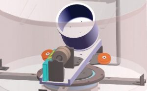 Figure 2: Interior of a Dual-Axis Centrifugal Mixer
The surface of the water in a cup remains perpendicular to the force of gravity, acting on it regardless of the angle at which the cup might be held. The surface of the material in the mixing container will remain perpendicular not to the force of gravity, but to the stronger centrifugal force created by the orbital speed of the container. The centrifugal force is a function of the distance from the center of rotation and the angular velocity. The dual-axis centrifugal mixer develops centrifugal acceleration in the range of 400 G. Due to the angle at which the cup is held, the distance between the center machine axis and any point on the surface of the product continually changes as the cup rotates. Product flows to compensate for these changes, resulting in flow patterns from the edge of the container to the center of the batch.
SURFACE FLOW
The mixing action of the dual-axis centrifugal mixer can be demonstrated with white and blue samples of children’s modeling compound. Approximately 80 grams of the blue and another 80 of the white were rolled into a ball, flattened into “hockey pucks” and placed into the mixing cup, with blue on the bottom and white on the top. The flow pattern observed in a traditional single-shaft mixer includes a vortex in or around the center of the mixing container.
[caption id="attachment_637" align="aligncenter" width="300"]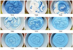 Figure 3: Surface Flow Pattern[/caption]
INTERNAL FLOW
Similarities are also evident within the batch, as can be seen when the mixed sample is cut in half (see Figure 4). The material travels down the center of the product and is deflected outward toward the wall by the container bottom. It then travels up the vessel wall and back across the surface of the product, as described in the previous section. [caption id="attachment_638" align="aligncenter" width="300"]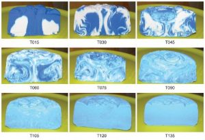 Figure 4: Internal Flow Pattern[/caption] After T015 (15 seconds), the blue material, which was originally at the bottom of the container, has traveled up the wall of the vessel, across the top, and down the center of the product. By T030 (30 seconds), a mixture of blue and white material follows a similar path. This mixing continues until T135 (2 minutes, 15 seconds) when a uniform product is produced.
REAL-WORLD MIXING
This type of mixer functions well in real-world operations, which often requires the mixing of many dissimilar components. Figure 5 illustrates the mixing of a series of powders, pastes, and liquids at a total mix time of 45 seconds. Typically, a 20-minute batch time is considered excellent for a traditional shaft-type mixer with much lower viscosities. [caption id="attachment_639" align="aligncenter" width="300"]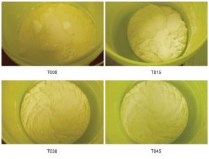 Figure 5: Powder, Paste and Liquid Mixing[/caption] The dual-axis centrifugal mixer produces the axial flow patterns that are predominant in liquid mixing while overcoming the viscosity limitations of a traditional single-shaft mixer. Added benefits include reduced cleanup requirements, as all shafts are eliminated and the container remains the only contact part. Without shafts, it is possible to produce very small batches; standard units are capable of mixing batches as small as 50 grams and as large as 2,500 grams. (These batch limits can be extended with container adapters.) In addition, the shallow vortex eliminates additional air entrainment during mixing. As vortex depth is not a limiting factor, the dual-axis centrifugal mixer can mix at high energy levels, which results in shorter batch times. In the adhesive and sealant industry, the mixer has been used for fast and efficient formulation qualification, pilot development, and small batch production.
Schmidt, Stephen T. "A Better Mix" Adhesive & Sealants Industry Magazine, 1 July 2010.

Posted in:
Mixing and Dispersion
Leave a comment
Related posts
 What to consider when moving to an Inverter
Inverters offer many benefits over traditional mechanical drives with fewer moving parts, larger speed ranges,...
Read more
JACKETED TANKS AND THERMAL SHOCK
Rapid changes in temperature of the heat transfer media can thermally shock the equipment. Typically, thermal shock...
Read more
Disperser Blade Mounting
To transfer torque from the shaft to the blade, manufacturers use a number of configurations. The two most common are...
Read more
DISPERSER CONFIGURATION
The design of a dispersion system begins by defining the batch size and product characteristics. From there we can...
Read more
Tip Speed Definition and Formula
Blade Speed (tip speed), measures how far a point on the outer most edge of the disperser blade travels in a given...
Read more